3U Server Power Supply Replacement
BackgroundPlease refer to Troubleshooting Power Issues for help with a 3U server that does not power up properly. If the issue is due to a failed power supply, contact your local Kaleidescape dealer for service kit availability. The following procedure details how to install a 3U power supply replacement (SVC-KIT-0130).PreparationBefore you begin, you will need:
Service Kit Parts
- Power Supply with Mounting Bracket
- Power Inlet Plate
- Heatsink Fan
- 3-Fan Bracket Assembly
- 5-Fan Bracket Assembly
- Tie Wrap
Tools Required
- #1 and #2 Philips Screwdriver
- #2 Short Philips Screwdriver
- Utility Knife
- Clean, dry cloth
- Vacuum with small, soft dusting attachment
- Canned air (multi-purpose duster safe for electronic circuitry)
- Electrostatic discharge (ESD) wristband or other ESD protection
ProcedurePower off Server and Remove Disk Cartridges
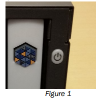
1. Open the front panel and press the POWER button to turn off the server.
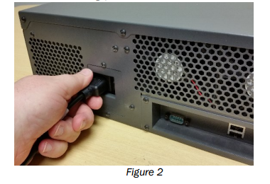
2. Disconnect all cables including power cord.
3. Press the eject buttons on the disk cartridges.
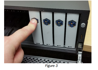
4. Gently slide each disk cartridge out of the slot.
WARNING Avoid touching the exposed connector at the back of the disk cartridge. Static electricity can damage the electronics inside the disk cartridge.
5. Place the disk cartridges on a well-padded, anti-static surface. Do NOT stack disk cartridges.
WARNING Disk cartridges can be damaged by even a slight bump. Extreme care must be taken at all times when handling the disk cartridges, especially when inserting, removing, placing on a surface, or when cleaning. Failure to observe precautions can result in damage to the drive and loss of content.
6. Remove unit from rack (if required).
7. Cut through the round warranty sticker, usually applied to the side of the unit, with a knife.
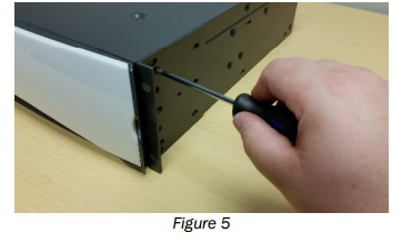
8. Remove rack ears from chassis.
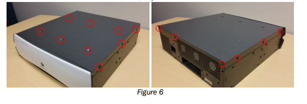
9. Remove 15 screws from the sides, top and rear of the chassis.
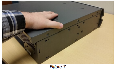
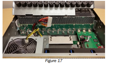
10. Slide the lid toward the rear of the chassis and lift to remove.
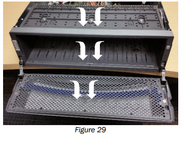
Remove the Top Fan Bracket
1. Remove the three screws on the front lip of the fan tray.
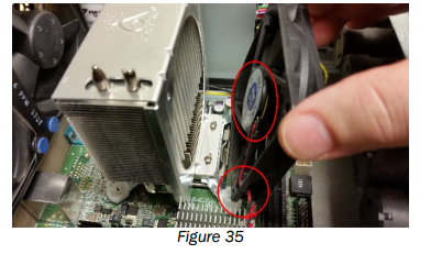
2. Remove the two screws (one on each side) that are securing the fan bracket and carefully lift fan tray up to expose the fan connector.
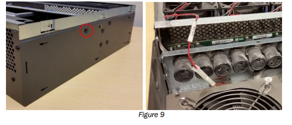
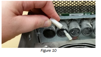
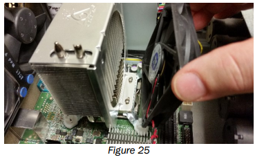
3. Disconnect the existing fans from the power supply.
Remove Ejector Bracket
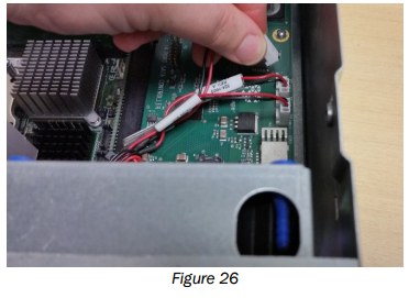
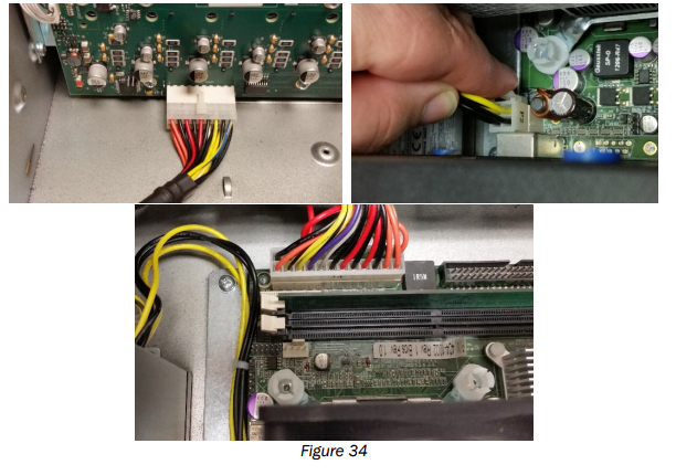
1. If necessary, carefully extract the motherboard power cable from under the ejector housings.
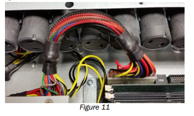
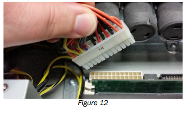
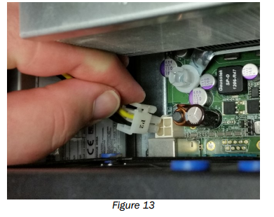
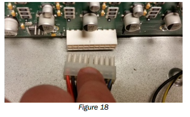
2. Unplug the main motherboard power by pressing the latch on the front to release it and pull upwards from motherboard.
3. Unplug the 4-pin motherboard CPU power by pressing the latch on the front to release it and pull upwards from motherboard.
4. Remove the two inside screws securing the ejector bracket by using a thin Philips screwdriver inserted between two ejectors nearest the screws or use a right angle screwdriver.
5. Remove the four Philips screws securing the ejector bracket. Two on each side.
6. Pull the bracket gently toward the rear of the chassis until the ejector rods are cleared.
7. Lift the ejector bracket out of the chassis.
8. Unplug the backplane power connection by pushing down on the latch and pulling out connector.
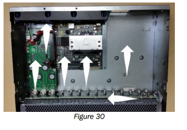
Remove the Power Supply
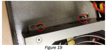
1. Remove the two screws inside the chassis on the front of the power supply, if necessary. Not all power supplies use these screws.
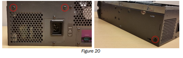
2. Remove the two screws on the rear and one on the right side of the chassis.
3. Lift the power supply out.
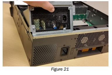
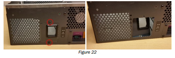
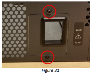
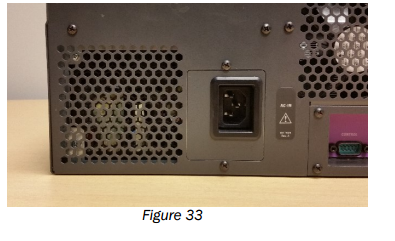
4. Remove the Power Supply Inlet Plate by removing the two screws above and below the plate. Push the plate into the chassis and remove.
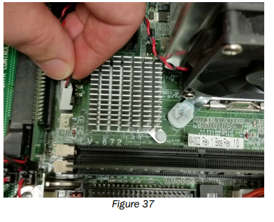
Remove the Heatsink Fan
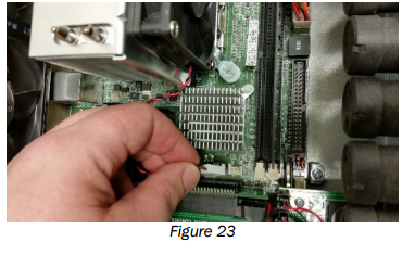
1. Carefully unplug the heatsink fan.
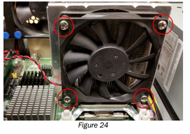
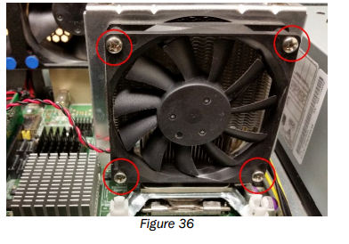
2. Use a short or right angle screwdriver to remove the screws holding the heatsink fan on. Be careful not to drop the screws onto the motherboard.
3. Remove fan from chassis.
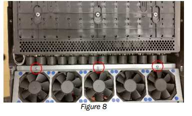
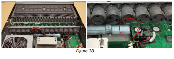
Remove the Rear 3-Fan Bracket
1. Carefully disconnect the three fan connectors and cut any tie wraps that are securing the wire bundle.
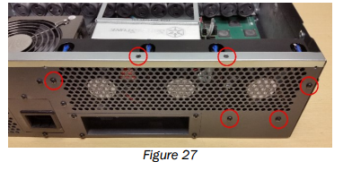
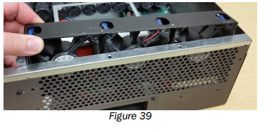
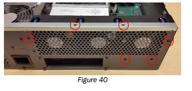
2. Remove the 2 top screws securing the rear fan bracket to the chassis rear lip. Remove the 4 screws securing the rear bracket to the back of the chassis.
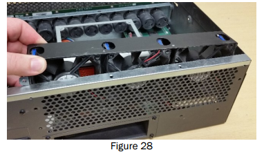
3. Lift the bracket out being careful not to damage the heatsink.
Clean the Disk Cartridges and Chassis
1. Wipe the inside of the chassis lid clean.
2. Vacuum the grill on top of the drive cage.
3. Vacuum the inside of the drive cage with small, soft dusting brush attachment.
4. Vacuum the front panel, front and back.
5. Use canned air to blow air between the drive cage and the drive backplane. Avoid touching the circuit board.
6. Use canned air to clean the fins of the heatsinks.
7. Use canned air to clean the circuit boards. Hold the can at least 6 in. from the board and blow air out the chassis rear vents.
8. Blow canned air through the power supply area from the inside, blow air out the rear vents.
Install New Power Supply
1. Install the new provided Power Inlet Plate from the inside of the chassis with the opening in the upper right corner. Secure with the two Philips screws previously removed.
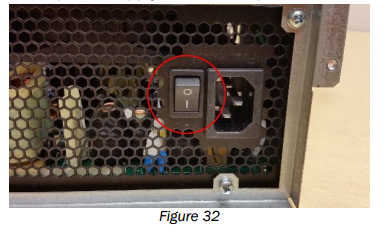
2. Make sure the new power supply is in the ON position.
3. Place new power supply into position in the chassis ensuring the power entry aligns with the opening in the plate previously installed. Make sure no cables are caught under the supply. Secure with the three screws as detailed in figure 20. The front two screws inside the chassis are not used with this new power supply.
4. Reconnect the backplane, CPU and Motherboard power connectors.
Install New Heatsink Fan
1. Align the new heatsink fan with the label toward the heatsink and fan wires exiting the fan from the lower left corner.
2. Install the 4 screws to secure the fan to the heatsink. Be careful not to overtighten the screws or touch the motherboard.
3. Reconnect the fan cable to the motherboard.
Reinstall the Ejector Bracket
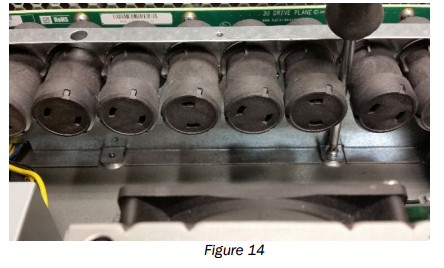
1. Replace the ejector bracket. Be careful not to touch any of the circuit boards. Ensure all 14 ejector rods are inserted into the holes in the backplane and the bracket is aligned.
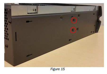
2. Secure the ejector bracket by reinstalling the 4 external black Philips screws and the two internal silver Philips screws as seen in figures 14 and 15.
Install New Rear 3-Fan Bracket.
1. Place the new 3-Fan bracket with the wires pointed away from the power supply. Be careful to avoid damaging the heatsink or pinching the wires.
2. Reinstall the 2 flathead top screws and 4 panhead screws securing the new rear bracket.
3. Connect the fans to the connectors. The order is not important. Ensure the fan wires are positioned so they do not interfere with the fans and secure with provided tie wrap.
Install New 5-fan Bracket Fan
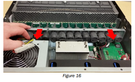
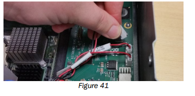
1. Connect the fan assembly to the power supply. Ensure the connector is fully engaged.
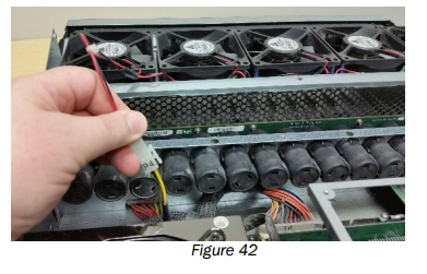
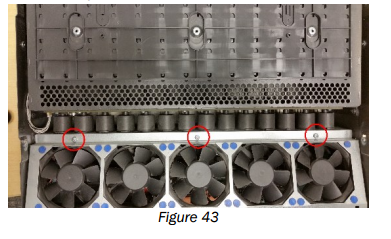
2. Reseat the fan bracket aligning the screw holes on the front lip of the fan tray. Ensure no cables are pinched or interfering with the fans. Secure bracket with the three lip screws.
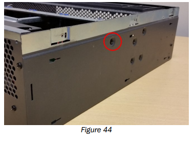
3. Install the two side screws of the fan bracket. One per side.
4. Unit can be briefly connected to power and turned on to ensure the fans are spinning and quiet.
5. Press the power button to turn off the server and unplug the unit.
Reattach Chassis Lid and Reinstall Disk Cartridges
1. Align the chassis lid. Slide the lid forward and fully into place. See Figure 7.
2. Reinstall screws on the rear, top and sides. 15 screws total. See Figure 6.
3. Reinstall rack ears. See Figure 5.
4. Reinstall unit in rack, if necessary.
5. Verify that the latch on the disk cartridge, the gray plastic wedge that extends from the top of the cartridge, works properly. The latch is designed to retract when the Kaleidescape logo (or white button on a blank) is pressed, and to pop up and engage with the chassis when a disk cartridge is inserted. If the latch sticks in the retracted position, the disk cartridge does not lock in place and cannot operate properly.
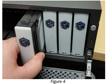
6. Reinstall disk cartridges. Align the disk cartridge to the slot correctly. The latch goes to the top with status lights to the bottom. See Figure 4.
7. Push firmly but gently in the middle of the cartridge until the cartridge clicks into place. Do NOT slam the cartridge in.
8. Close front cover and reconnect power cord and network cable.
